Sunday, 11 February 2018

How CPU works

A computer is a electronic device which processes the data and executes instructions, Every modern day computer has a processor, primary memory, secondary memory, Input and Output Devices.
The processor is the brain of the computer, it is the place where all the instructions gets executed.

For the processor, everything is 0's and 1's,all the inputs and  outputs are suitable combinations of 0's and 1's. The processor have the suitable electronic circuits to process these 0's and 1's. Let's say we type word  "A"  in the keyboard, the letter  'A' will have suitable ASCII value  "044", similarly every  alphabet has suitable ASCII value which will be converted to corresponding  binary value for processing. For the output let's take Color "Red" it has suitable Hex value  #ff0000, which can be converted to binary  Now let us see how CPU process these 0's and 1's.

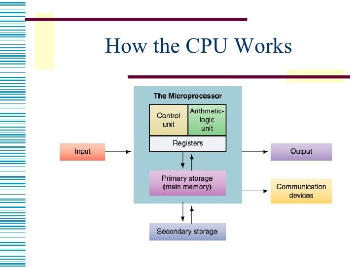
 The processor has Arithmetic and Logic circuits, Control circuits,  Memory registers and buses for transfer of the data. Consider it as a artificial brain, where the  registers contains information  for processing, The arithmetic and Logic circuit  performs Arithmetic and Logical operations. The control circuit controls the execution of instructions,  The buses is similar to nerves of human body which is used to transfer the data within processor and between processor and memory,  I/0 devices.

Arithmetic and Logic Circuit

The Arithmetic and Logic circuit is made of circuit like adder,subtractor  and other digital logic circuits. These digital logic circuits are made up of logical gates like AND,OR,NOR,NOT,NAND,XOR,XNOR. These logical gates is made up  of transistors. The Transistor is simple electronic device which has three terminals, namely Base, Emitter and Collector. Based on the Base Voltage,The collector-Emittor Voltage can be controlled.This circuit is called Transistor as switch. This forms the base for all the logical circuits to work. The Processor is made up of millions and millions of transistor.

CPU Registers

The processor register is one of the smallest set of data holding places inside the CPU, The registers hold the instructions, data address other data fields. The 32 bit execution or 64 bit execution depends on the size of the processing registers.

Control Circuit


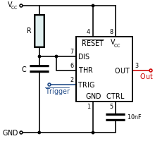
The speed of the processor depends on the control circuit which  triggers the processors, this speed is called clock speed, for a 1.7 GHz processor, the speed is 1700000000 cycles per seconds, ie( one billion, seven hundred million cycles per second), this means the CPU processes more than 1 billion instructions per second,  this makes the computer incredibly  fast and multitasking. 

Memory and I/O Operation

The memory inside the processor cannot store lots of data, so there is need for the external memory, this is where the RAM,ROM comes in to place, The ROM is Read Only Memory where the operations like BIOS(Basic Input/Output System) initializing the hardware while boot-up are done. The data inside the ROM is non-volatile. The RAM is another  primary memory for the processor, All the data during program execution is stored in the RAM, the Processor reads data from the RAM and processes it.The data inside the RAM is volatile,after execution from the CPU the OS releases the memory.

For Reading the I/O devices the suitable device drivers is needed for communication between the I/O device and the processor. The device driver raises a suitable interrupt for reading the data from the input device and based on the the processor reads the data, there are specified registers allocated for Input and output operations.

CPU Bus


  The CPU has three types of bus namely Data bus, Address bus and control bus, The address bus is unidirectional bus where the CPU writes the memory address in which the data needed to be read/write. The data bus is used to transfer the data between memory,I/O devices and CPU. It's is bidirectional bus, the data flows to and from the CPU. the control bus carries commands from the CPU and returns status signals from the devices. If the appropriate device is read or write the corresponding  control bus will be active.

The block diagram summarizes  the working of CPU.


Image result for how cpu works


In recent years there are many advanced multi core processors, they have more than one processing unit for processing, which makes the computer extremely fast and efficient.


 Now processor need someone to organize all the things properly and utilize it properly, this role is done by a software called operating System, the main task of the operating system is to manage the CPU resources, allocating memory, it's like the bridge to reach the CPU. The operating system itself resides inside the main memory and performs all these operations. Without Operating system the CPU will not know what to do.

Anyone could wonder, how even a single core processor could able to do many things  in parallel. One may use MS word while playing music in the background, this is taken care by operating system, the OS maintaines queue of tasks that needed to be executed,based the task queue it swiches the execution of task frequently it will look like all the process is running in parallel. This switching is done in nano seconds. There are many scheduler algorithms OS uses for the scheduling of tasks.


This is the basic introduction of how CPU works, there is lot more to learn and know.

Thanks,
Aravind


Saturday, 25 June 2016

Overview of Internet of things

There is huge buzz around the technologist about the Internet of things, and it is predicted that the IOT will have a huge impact on the IT industry and will significantly contribute to it's development, and it is expected that by 2020  20-30 billion devices will be connected to the internet and will have huge and direct impact on the people.Now let us see what IOT actually is and how it works.

The Internet of things is nothing but connecting physical world to the internet,The physical world means that it can be anything for example a door, a car, a fridge etc. At first anything that wants to communicate via internet should have a IP address assigned to it. It is obvious that a fridge or door will not have any IP address,so we need some method to communicate with non IP devices, for that a gateway is used, the gateway acts as an interface between the physical devices and the cloud,let us see about this in later part of the article.

Now let us see a example to illustrate the concept of Internet of things, let us assume that you have a golden chair and you would like to monitor the chair continuously, but for some reasons you may need to go to some other place and still you would like to monitor the chair, so in this case the Internet of things comes in to the picture,now what you can do is you can make your golden chair as a thing of the internet and we can monitor the status of the chair via internet from anywhere anytime,this is the small example of the application of Internet of things,it has a huge potential to solve the many real world problems and can improve the quality of living.

In the above example the status of the chair is monitored, but how can chair send it's status, as chair cannot  generate any data on its own, but we can make chair to generate the data with help of the sensors, sensors are the one which converts physical parameters in to electrical parameters, so we can connect appropriate sensors to the chair and can get the data, for example a pressure sensor can be connected to the chair to get the data of whether someone  sits on chair, a door sensor can be connected on the door to get the data of whether someone has opened the door. so we are getting the data from the physical device via the sensors connected to it.

The data is collected form the physical object via sensor and still we have one more task that is pushing the data to the cloud to do this we need a gateway device to get the data from the sensor and process the data and push the meaningful data to the cloud. Here the gateway device will act as a interface between the sensors and the cloud.The gateway device should be loaded with the suitable software to collect the data from the sensor and push it to the cloud,and gateway device should also be connected to the internet, The IP address of the server(cloud solution) should be known to the gateway device and it can push the data to it. So in the internet of things applications, the physical world gets IP address via gateway device and via gateway device it can send the data to the cloud.

Simplified Representation of implementation of IOT

                                          wired  or wireless                                          Internet            
Physical object --->Sensors-----------------> GATEWAY DEVICE -------------->CLOUD --- >USER

So from the above representation  it can be seen that physical device is connected to sensors and sensors is connected to gateway device and gateway device has internet connection enabled and with help of the gateway device the data can be pushed to cloud and from the cloud the data is viewed by the user via his mobile phone or computer. In the connection between the sensors and the gateway device it can be wired or wireless connection, the wireless connection can be Zigbee, Wi-Fi etc.
There various types of sensors.
Digital Sensor
Analog Sensor
RS485, RS232, RS422 communication enabled meters.
The Digital sensor are the one which gives either HIGH OR LOW signal, typical example is Door sensor representing open or close.
The Analog Sensors are which gives varying values such as pressure sensor, LDR, these sensor gives varying value based on the physical parameter.
The RS485 type or similar communication standard sensors can be useful for getting the data from the meters such as Energy meter, fuel meter etc.
In case of the energy monitoring, the energy meters which supports the RS485 or with other modes of communication can be connected to the gateway devices directly and communication can be established with help of the protocols like MOD-BUS, and the gateway device can collect data from the energy meter and push it to the cloud. Similarly for monitoring such Fuel level or water flow level can be measured with help of the corresponding meters with RS485 or other communication and MOD-BUS or similar protocol support.
The next important things is gateway devices,let us see small description about gateway devices
There are lot of IOT Gateway devices available, and Raspberry pi, a credit card sized mini computer famous among the electronic hobbyist can also be used a gateway device and suitable coding should be done to get the data from the sensor and push it to the cloud.

Applications of Internet of things

The Internet of things has a lot of potential application in the field of Power, security, smart cities and smart homes. For example a power plant can be completely monitored, a industry can be completely monitored, similarly there are lots and lots of solutions for real world problems and can vary based on the peoples needs.

Thank You


Friday, 24 June 2016

Getting Started with Raspberry PI


The field of embedded System is continuously evolving and lot of improvements and features are getting added up. The Raspberry pi is one of the important embedded system device and evolving as Internet of Things gateway device.

Hardware Description of Raspberry Pi

The Raspberry Pi is next generation credit card sized mini computer with many features as conventional computer and also has GPIO pins that can be used for Microcontroller applications.
The Raspberry Pi has ARM Cortex processor, the single core processor with 700 MHZ clock frequency is used in Raspberry Pi 1 and Quad core processor of clock frequency 900 MHZ and 1200 MHZ is used in R-Pi 2 and R-PI 3 respectively.
The memory is provided to raspberry pi by external SD card, The SD card is also loaded with suitable operating system, the most popular and preferred operating system is Raspbian.
The Pi also has USB ports which enables us to connect keyboard, Mouse , Pen drive, and it also has a HDMI slot to connect the monitor and one slot for camera interface and it also has one slot is provided for connection the LAN cable to access the internet. The Raspberry Pi can be powered by suitable power adapter of prescribed voltage rating.


Various operations on Pi

As described earlier Pi is a mini computer, you can do certain operations as you do in your computer,
like creating a file, deleting file and we can write own program and run it.

If Raspian or other Linux distributed OS is installed, In LX terminal we can perform various operations in raspberry Pi, to create a directory use the command mkdir dirname, for example mkdir pi. To go in to the directory use the command cd, the command "cd pi" will go in to the directory pi.  To Write a C program and run it, first open a suitable editor either "vi" or "nano",Eg "nano helloworld.c" and write your C program and save the program. To save the program in vi editor press Esc and ":wq".To save the program in nano editor press "ctrl+x". To compile the program "gcc helloworld.c" now object file will be created and to run the program type "./a.out", the output will be displayed on the screen.To install any package we can use the following command "sudo apt-get install 'packageName'",for example to install sqlite3 database "sudo apt-get install sqlite3", this will install sqlite3 database in raspberry pi. To install some third-party packages we can use the wget command to install the package.

Accessing GPIO pins

The Raspberry Pi has GPIO( General Purpose Input Output)  pins that can be used to give digital Input or allows us to take digital output. The number of GPIO pins varies from one model of raspberry Pi to another.
The important point to be noted is Analog inputs cannot be given directly to the Raspberry Pi, so we need external device(such as Expander Pi) to read analog input.There are two ways of numbering the I/O pins in Raspberry Pi within RPi.GPIO. The first is using the BOARD numbering system. This refers to the pin numbers on the Pi header of the Raspberry Pi board. The advantage of using this numbering system is that your hardware will always work, regardless of the board revision of the R-Pi. You will not need to rewire your connector or change your code. The second numbering system is the BCM numbers. This is a lower level way of working - it refers to the channel numbers on the Broadcom SOC. You have to always work with a diagram of which channel number goes to which pin on the RPi board. Your script could break between revisions of Raspberry Pi boards.

To access GPIO pins we need to install RPI.GPIO python library. The RPI.GIPO is installed by default in Raspbian, to ensure that it is in the latest version please follow the following steps

1) sudo apt-get update
2) sudo apt-get install python-rpi.gpio python3-rpi.gpio
3) sudo apt-get install python-dev python3-dev

These three command is needed to access the raspberry pi GPIO pins with help of some python code.

Now let us see some python code to write and read digital pins,

Now Let us see simple program that is to set the digital output

import RPi.GPIO as GPIO ## Import GPIO library
GPIO.setmode(GPIO.BOARD) ## Use board pin numbering
GPIO.setup(7, GPIO.OUT) ## Setup GPIO Pin 7 to OUTGPIO.output(7,True) ## Turn on GPIO pin 7


First line of code is to import the library that allows to use to access the GPIO pins via python script
then then the Board pin Numbering is used, to use the BCM pin numbering use the following command GPIO.setmode(GPIO.BCM). The next line of code is to set the particular pin as output and to turn on the pin True is used, to turn off the particular pin False is used. 

Let us another pin used to read digital input

import Rpi.GPIO as GPIO
GPIO.setmode(GPIO.BCM)
GPIO.setup(23, GPIO.IN, pull_up_down = GPIO.PUD_DOWN)
GPIO.setup(24, GPIO.IN, pull_up_down = GPIO.PUD_UP)
while True:
if(GPIO.input(23) ==1):
print(“Button 1 pressed”)
if(GPIO.input(24) == 0):
print(“Button 2 pressed”)
GPIO.cleanup()

To read the input, we need to specify whether the pin is used as Pull_up or Pull_down, these specification is very much necessary to set the particular pin as input. The while true indicates its a infinite loop and GPIO.input(23) is used to read the pin number 23. similarly same is used for pin number 24.

So these are the very basic operations that are performed on the raspberry pi, the raspberry-pi has more capabilities and  can act as IOT gateway device. 

Thank You


Thursday, 14 January 2016

How to Repair mosquito bat

First open the mosquito bat by using screwdriver, Inside bat we will find simple power electronic circuit, consisting of battery, Transistor, resistors, capacitors , diodes and small transformer.The basic function of this circuit is to generate very high voltage across output and electric fence so mosquito will die immediately when it came in contact with fence.
We need a digital Multimeter to check the various electronic components. 
Caution: Never keep Multimeter probes directly on  the electric fence, it may result in damage to Multimeter and even we may face some shock.

Image showing circuit of mosquito bat

Picture of Open the case and examine the circuit board


First Remove the battery and test the battery carefully, check voltage of battery,  if it is a 3 V(DC) battery, when you check with Multimeter it should show same  rated voltage( in fully charged condition), if it indicates 0 or low value  then battery is damaged.

After removing battery, now test the electronic components, for testing electronic components  keep the Multimter in continuity mode, You will hear a buzzer sound when you one probe is touched with other. In continuity mode of Multimeter we can find short Circuits ,suppose if you test a diode and if you hear buzzer sound then diode is short circuited indicates it is damaged.

Now with the help of Multimeter test all the components, in mosquito bat there is less chance of failing of transformer.so first test all other components

In mosquito bat there is more chance of failing of transistor, so check  the transistor  and if it is damaged replace it.
How to check the transistor-
It is better to check the transistor after removing it, So Desolder the transistor from circuit board with help of soldering rod.(Please be careful while using soldering rod,if you have no practice of using it better avoid it using) or use Desoldering tool to remove it carefully.
For NPN transistor Keep one probe(Red) on Base and other(Black) on emitter, Multimeter should indicate some resistance value, when we reverse the probe(Red probe on emitter and Black on Base) it should indicate "1"  Next keep  probe(Red)on base and other(Black) on collector, Multimeter should indicate value and  when you reverse the probe Multimeter should indicate "1" .Now keep one probe in Emitter and other in Base , Multimeter should  indicate value  "1"   and  if you reverse the probe Multimeter should indicate the same-: "1".

For PNP type transistor  when probe(Red) on emitter and black on base it should indicate resistance value and  when black probe on emitter and Red probe on base it should indicate "1".Next keep  probe(Red)on base and other(Black) on collector, Multimeter should indicate "1" and  when you reverse the probe of multimeter , Multimeter should indicate resistance value.  Now keep one probe in Emitter and other in Base , Multimeter should  indicate value  "1"  and if you reverse the probe Multimeter should indicate the same-: "1".
If the transistor passes above test it is perfectly good.while testing if you hear a buzzer sound then transistor is damaged, you have to replace new transistor. While replacing please note the number written in transistor(Eg BC 547) and replace it with same number.
From the number of transistor we can find it whether it's NPN or PNP type transistor by checking it's data sheet.

Image showing testing of transistor( But it is not in continuity mode)

Image result for testing bipolar transistor with digital multimeter

After testing of transistor, test the  capacitor, keep one end of capacitor with one probe and other end of capacitor with other probe, in continuity mode if it indicates short circuit ( buzzer sound), capacitor is damaged and we have to replace the capacitor.same way test the diode also.Replace capacitance of same capacitance(in farad) and voltage rating.In similar way test the diodes also.

so replace the electronic component which has failed and connect the battery again and close the bat.Now the mosquito bat should be working

Thank You


Sunday, 27 December 2015

Getting started with Arduino

Introduction to Arduino


Arduino is an open-source prototyping platform based on easy-to-use hardware and software. Arduino is simple to learn and easy to use and we can do many innovative projects with help of arduino. An Arduino board historically consists of an Atmel  8-, 16- or 32-bit AVR  microcontrollerTo do programming in arduino we have to use arduino programming language and arduino software(IDE).We write our program in arduino software(IDE). The Arduino IDE supplies a software library called "Wiring" from the Wiring project, which provides many common input and output procedures.
There are various types of arduino boards available like arduino uno, arduino mega, arduino nano, arduino le0rnado  etc. Based on our need we can choose particular board. Let us start our learning by simple and effective arduino board - arduino uno.
Arduino also has some shields which can interfaced with arduino for specific purpose like GSM shield for using GSM, Ethernet shield for internet. Wifi shield for connecting arduino with wifi etc.these shields are readily available and can be easily interfaced with arduino.

Arduino uno

The Arduino uno has ATMEGA328P microcontroller. To power the arduino simply connect it with USB cable or use proper adaptor for power supply.The operating volate is 5V DC. There are 14 digital I/O pins where we can give digital input or we can take digital output. and out of these 14 pins 6 pins are PWM(pulse width modulation)pins.and there are six analog input pins where we can give analog input.it is used when we are using an analog sensor like temperature or pressure sensor. we can connect these sensors to analog input pins.it also has Rx and Tx pins used for serial communication.which can be used while connecting with GSM. To power the arduino simply connect it with USB cable or use proper adaptor for power supply.The operating volate is 5V DC. Arduino uno uses 16 MHZ quartz crystal for clock input.

Image of Arduino uno


Image result for arduino uno


Programming in Arduino


Let us start by simple program blinking of LED

# define LED_PIN 13
void setup() 
{
pinMode(LED_PIN, OUTPUT); // Enable pin 13 for digital output
}
void loop() 
{ 
digitalWrite(LED_PIN, HIGH); // Turn on the LED 
delay(1000); // Wait one second (1000 milliseconds)
digitalWrite(LED_PIN, LOW); // Turn off the LED 
delay(1000); // Wait one second
}


let us assume that a LED is connected to pin 13.This is the simple program to make led blink for every second.At first we are defining pin no 13 as LED_PIN. we can define it by any name like #define LED 13; or #define Light 13.what ever name we are defining we have to use that in our program.instead of # define we can also use like this -  int LED_PIN=13; or # define LED_PIN 13.

Every arduino program has two functions
1) void setup()-Runs only one
2)  void loop()- runs infinitely 

In void setup() we will be assigning whether given pin is used as input or output.so in this program we have assigned LED_PIN( pin 13) as output.so this pin should be used as output not as input.

void loop ()- our actual coding starts here, we write our program/logic here.In the above program first statement of void loop () is digitalWrite(LED_pin, High). The function of digital write () is to make specified pin high or low.In above statement  pin 13 will be high and LED which is connected to pin 13 will glow.and next we are calling delay function, here we are providing a delay of 1 second,so pin will remain high for at least one second, the next statement is digitalWrite(LED_PIN, LOW);, this will make pin 13 as low and LED will turn off and again we are calling delay function, so LED will be off for at least one second.This code keeps on repeating indefinitely and LED continuously blinks.

Here we are connecting LED to pin 13 directly, suppose if we want to automate a Big lamp, we can connect it directly because Lamp will not glow in 5 Volt output from arduino, so for this purpose we need to use a transistor and a relay. Here transistor will act as a switch, base of transistor is connected to output pin of arduino and if output of arduino is high,  transistor will turn on and relay coil is connected to output of transistor will be energized and with help of relay we can control lamp.if information about transistor is needed refer my article on transistor.

Next let us see another simple program 

int LED_pin =13;
int inpin=7; 
int val=0;
void setup()
{
pinMode(LED_pin,OUTUPT);// enable pin 13 for digital output
pinMode(inpin,INPUT);// enable pin 7 for digital input
}
void loop()
{
val=digitalRead(inpin); // read the digital value and store it in val
digitalWrite(LED_pin,val); // turn on or turn off the led based on the value from val.
}

 Let us assume an LED is connected to pin 13 and a digital input is connected to pin  7.
Here first we are defining LED_pin as 13 and inpin as 7, and we are declaring a variable val.and in setup() part we are defining LED_pin as output and inpin as input. and loop part first statement is 
val=digitalRead(inpin);this will read digital value from the pin no 7 and store it in variable val, the function digitalRead() is used to read value from the specified  digital pin either high or low.and next statement is digitalWrite(LED_pin,val); it means the LED_pin will be high if val is high, ie if input given to pin no 7 is high then value stored in val is high and if input is low and value stored in val is low. so based on the value on "val"the LED connected to pin no 13 will turn on or off.

Saturday, 26 December 2015

How 555 timer works

In most of the industries operations are scheduled according to specific time requirements.In process industry,raw material is processed in different stages.In each stage, raw material is processed at particular time period. so for example process may be heating process and heat may required for 5 minutes.so there is number of applications specific delay is needed. the popularly used electronic circuit of providing delay is 555 timer.and with help of 555 timer we can do many electronic projects as well.

The 555 timer IC is an integrated circuit (chip) used in a variety of timer, pulse generation, and oscillator applications. The 555 can be used to provide time delays, as an oscillator, and as a flip-flop element.lot of electronics projects also done  using 555 timer

PIN DIAGRAM OF 555 TIMER


pin description:


Pin 1 (Ground):
Connects to the 0v power supply.

Pin 2 (Trigger):
Detects 1/3 of rail voltage to make output HIGH. Pin 2 has control over pin 6. If pin 2 is LOW, and pin 6 LOW,  output goes and stays HIGH. If pin 6 HIGH, and pin 2 goes LOW, output goes LOW while pin 2 LOW. This pin has a very high impedance (about 10M) and will trigger with about 1uA.

Pin 3 (Output):
(Pins 3 and 7 are "in phase.") Goes HIGH (about 2v less than rail) and LOW (about 0.5v less than 0v) and will deliver up to 200mA.

Pin 4 (Reset):
Internally connected HIGH via 100k. Must be taken below 0.8v to reset the chip.

Pin 5 (Control):
A voltage applied to this pin will vary the timing of the RC network (quite considerably).

Pin 6 (Threshold):
Detects 2/3 of rail voltage to make output LOW only if pin 2 is HIGH. This pin has a very high impedance (about 10M) and will trigger with about 0.2uA.

Pin 7 (Discharge):
Goes LOW when pin 6 detects 2/3 rail voltage but pin 2 must be HIGH. If pin 2 is HIGH, pin 6 can be HIGH or LOW and pin 7 remains LOW. Goes OPEN (HIGH) and stays HIGH when pin 2 detects 1/3 rail voltage (even as a LOW pulse) when pin 6 is LOW.  (Pins 7 and 3 are "in phase.") Pin 7 is equal to pin 3 but pin 7 does not go high - it goes OPEN.  But it goes LOW and will sink about 200mA.

Pin 8 (Supply):
Connects to the positive power supply (Vs). This can be any voltage between 4.5V and 15V DC, but is commonly 5V DC when working with digital ICs. 


Modes of operation


1) Bistable mode


2 )Monostable mode


3)  Astable Mode

Bistable mode


Image result for bistable mode of ic 555

fig:showing bistable mode of 555 timer

The 555 timer in bistable mode is also known as a flip-flop circuit. A flip-flop circuit alternates between two stable states, in this case the output of electrical current from the output pin.There are only two stable states (on and off) controlled directly by the trigger pin and reset pin.Here no external resistors or capacitors is connected.

Astable Mode


555 timer as astable multivibrator


An astable mode of 555 timer, often called a free-running multivibrator, is a rectan­gular-wave generating circuit. Unlike the monostable multivibrator, this circuit does not require any ex­ternal trigger to change the state of the output, hence the name free-running. Before going to make the circuit, make sure your 555 IC is working. For that go through the article: An astable multivibrator can be produced by adding resistors and a capacitor to the basic timer IC, as illustrated in figure. The timing during which the output is either high or low is determined by the externally connected two resistors and a capacitor.in astable mode 2 and 6 is short circuited so no trigger is given.

The general application of astable multivibrator is it will act as square wave generator and duty cycle of the square wave can be controlled.and it can also be used to blinking on and off of light with specific frequency.
percentage duty cycle %D = (R1+R2)/(R1+2R2)X100
frequency of oscillations is given by f=1/T=1/0.693(R1+2R2)C

Monostable Mode


555 timer as monostable multivibrator


 In Monostable mode, external pulse is needed for timer.it is often called as one shot multivibrator. is a pulse generator circuit in which the duration of the pulse is determined by the R-C network,connected externally to the 555 timer
The circuit has only one stable state when trigger is applied, it produces a pulse at the output and return backs to its stable state. Here trigger pulse is applied at 2.
The pulse width is W= 1.1RC ,C in farads, R in ohms, t in seconds.

So electronic hobbyist can develop lot of projects using monostable multivibrator of 555 timer.for example  automatic turning on and off of TV, fan,light etc. here IR can be used as trigger pulse and 555 timer is connected in monostable mode and whenever the trigger is applied output is produced and it is given to transistor(here transistor will act as a switch) and it will in turn on the relay and necessary thing can be controlled.

Conclusion

NE 555 timer is very widely used in the various industrial applications and also in the electronic projects and it it is easy to start develop your own project using 555 timer.


Friday, 25 December 2015

How transistors work


transistor is a semiconductor device used to amplify or switch electronic signals and electrical power. It is composed of semiconductor material with at least three terminals for connection to an external circuit.A voltage or current applied to one pair of the transistor's terminals changes the current through another pair of terminals.
Bipolar transistor has three terminals 
1)Base-control signal
2)Emitter
3)Collector
A small current in the base of the transistor can control large current in the Collector and Emitter terminals.
Generally Bipolar junction Transistor can be classified in to two types
1)NPN Transistor, 2) PNP transistor
NPN transistor means Emitter-N type material, Base- P type material, Collector-N type material,
similarly for PNP transistor-Emitter-P type material, Base- N type material, Collector-P-type material,

Image result for transistor

Fig: showing NPN and PNP transistor
Note: if NPN or PNP is not mentioned, arrow mark towards base indicates PNP transistor.Arrow mark away from the base indicates NPN transistor.
For transistor to work-
1) Emitter- Base junction should be forward biased-Junction has low resistance,
2)Collector-Base junction should be reverse biased-Junction has high resistance.

In transistor Emitter is heavily doped, because it has to supply majority carries.and Collector and Emitter terminals should not be interchanged.and size of Collector is large as compared to base because it has to accept majority carriers.
Transistor can be operated for two purpose
1)Transistor as a Switch
2)Transistor as a amplifier


Transistor as a switch

Transistors are commonly used in digital circuits as electronic switches which can be either in an "on" or "off" state.
Because a transistor’s collector current is proportionally limited by its base current, it can be used as a sort of current-controlled switch. A relatively small flow of electrons sent through the base of the transistor has the ability to exert control over a much larger flow of electrons through the collector.

Image result for transistor as a switch
fig showing transistor as switch.
so with help of base current we can control the large collector current.

Practical application of transistor as switch

Light/ dark activated switch


Image result for light activated switch   


Here photo resistor or  LDR(Light Dependent Resistor) is used as sensor-property of LDR is resistance will decrease when light is applied(few hundred ohms) and resistance will increase in darkness(in mega ohms).
LDR is connected in series with 100 Kilo ohm resistor it forms simple voltage divider connection.
so in darkness voltage drop across Base-Emitter junction increases. so transistor Base-Emitter voltage is above cut off voltage and now transistor starts conducting and current flows through the LED.
similarly when light falls on LDR. Its resistance decreases and voltage across Base-Emitter junction of transistor decreases now transistor will not conduct and current through the LED is zero. and LED will not glow.so by this simple circuit we have made an automatic light which will glow only in darkness and automatically turns off in light. 


Transistor as an amplifier

Image result for transistor as an amplifier


fig:circuit of transistor as an amplifier
The common-emitter amplifier is designed so that a small change in voltage (Vin) changes the small current through the base of the transistor; the transistor's current amplification combined with the properties of the circuit mean that small swings in Vin produce large changes in Vout.
the transistor can be used as a current and voltage amplification.
current gain  hfe = Ic / Ib
A fairly low gain transistor might have a current gain of 20 to 50, while a high gain type may have a gain of 300 to 800 or more
Voltage gain  = change in collector voltage / change in base voltage.
so transistor as amplifier is explained,

Transistor Characteristics:


 Transfer Characteristics
 Input Characteristic.
 Output Characteristic.

Transfer characteristics:


X axis: Base current(mA)
y axis:  collector current(MA)


Transfer Characteristic

The graph of ICE / IBE shown (right) is called the TRANSFER CHARACTERISTIC and the slope of the graph shows the hfe for that transistor.

Input Characteristics:

X axis: Base-Emitter voltage(V)
y axis:  Base current(MA)

Input Characteristic

The INPUT CHARACTERISTIC (right), a graph of base emitter current IBE against base emitter voltage. Initially the transistor is not conducting because the voltage is below cut in voltage or knee voltage. when the voltage is above knee voltage base current flows.


 Output Characteristic.


X axis: Collector-Emitter voltage(V)
y axis:  collector current(MA)


Output Characteristic
 shows the OUTPUT CHARACTERISTIC whose slope gives the value of output conductance.for small values of base current the corresponding collector current is low and if base current is increased, collector current is also increased.

These are the various characteristics of transistor.

Conclusion

Most of the analog and digital electronic  circuits and logic gates  are build using transistors.so knowing the working of transistor is very important