In most of the industries operations are scheduled according to specific time requirements.In process industry,raw material is processed in different stages.In each stage, raw material is processed at particular time period. so for example process may be heating process and heat may required for 5 minutes.so there is number of applications specific delay is needed. the popularly used electronic circuit of providing delay is 555 timer.and with help of 555 timer we can do many electronic projects as well.
The 555 timer IC is an integrated circuit (chip) used in a variety of timer, pulse generation, and oscillator applications. The 555 can be used to provide time delays, as an oscillator, and as a flip-flop element.lot of electronics projects also done using 555 timer
PIN DIAGRAM OF 555 TIMER

pin description: | |||||||||
| Pin 1 (Ground): Connects to the 0v power supply. Pin 2 (Trigger): Detects 1/3 of rail voltage to make output HIGH. Pin 2 has control over pin 6. If pin 2 is LOW, and pin 6 LOW, output goes and stays HIGH. If pin 6 HIGH, and pin 2 goes LOW, output goes LOW while pin 2 LOW. This pin has a very high impedance (about 10M) and will trigger with about 1uA. Pin 3 (Output): (Pins 3 and 7 are "in phase.") Goes HIGH (about 2v less than rail) and LOW (about 0.5v less than 0v) and will deliver up to 200mA. Pin 4 (Reset): Internally connected HIGH via 100k. Must be taken below 0.8v to reset the chip. Pin 5 (Control): A voltage applied to this pin will vary the timing of the RC network (quite considerably). Pin 6 (Threshold): Detects 2/3 of rail voltage to make output LOW only if pin 2 is HIGH. This pin has a very high impedance (about 10M) and will trigger with about 0.2uA. Pin 7 (Discharge): Goes LOW when pin 6 detects 2/3 rail voltage but pin 2 must be HIGH. If pin 2 is HIGH, pin 6 can be HIGH or LOW and pin 7 remains LOW. Goes OPEN (HIGH) and stays HIGH when pin 2 detects 1/3 rail voltage (even as a LOW pulse) when pin 6 is LOW. (Pins 7 and 3 are "in phase.") Pin 7 is equal to pin 3 but pin 7 does not go high - it goes OPEN. But it goes LOW and will sink about 200mA. Pin 8 (Supply): Connects to the positive power supply (Vs). This can be any voltage between 4.5V and 15V DC, but is commonly 5V DC when working with digital ICs. | |||||||||
Modes of operation | |||||||||
| 1) Bistable mode | |||||||||
| 2 )Monostable mode | |||||||||
| 3) Astable Mode |
Bistable mode

fig:showing bistable mode of 555 timer
The 555 timer in bistable mode is also known as a flip-flop circuit. A flip-flop circuit alternates between two stable states, in this case the output of electrical current from the output pin.There are only two stable states (on and off) controlled directly by the trigger pin and reset pin.Here no external resistors or capacitors is connected.
Astable Mode
555 timer as astable multivibrator

An astable mode of 555 timer, often called a free-running multivibrator, is a rectangular-wave generating circuit. Unlike the monostable multivibrator, this circuit does not require any external trigger to change the state of the output, hence the name free-running. Before going to make the circuit, make sure your 555 IC is working. For that go through the article: An astable multivibrator can be produced by adding resistors and a capacitor to the basic timer IC, as illustrated in figure. The timing during which the output is either high or low is determined by the externally connected two resistors and a capacitor.in astable mode 2 and 6 is short circuited so no trigger is given.
The general application of astable multivibrator is it will act as square wave generator and duty cycle of the square wave can be controlled.and it can also be used to blinking on and off of light with specific frequency.
percentage duty cycle %D = (R1+R2)/(R1+2R2)X100
frequency of oscillations is given by f=1/T=1/0.693(R1+2R2)C
Monostable Mode
555 timer as monostable multivibrator
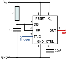
In Monostable mode, external pulse is needed for timer.it is often called as one shot multivibrator. is a pulse generator circuit in which the duration of the pulse is determined by the R-C network,connected externally to the 555 timer
The circuit has only one stable state when trigger is applied, it produces a pulse at the output and return backs to its stable state. Here trigger pulse is applied at 2.
The pulse width is W= 1.1RC ,C in farads, R in ohms, t in seconds.
So electronic hobbyist can develop lot of projects using monostable multivibrator of 555 timer.for example automatic turning on and off of TV, fan,light etc. here IR can be used as trigger pulse and 555 timer is connected in monostable mode and whenever the trigger is applied output is produced and it is given to transistor(here transistor will act as a switch) and it will in turn on the relay and necessary thing can be controlled.
Conclusion
NE 555 timer is very widely used in the various industrial applications and also in the electronic projects and it it is easy to start develop your own project using 555 timer.
No comments:
Post a Comment