Saturday, 25 June 2016

Overview of Internet of things

There is huge buzz around the technologist about the Internet of things, and it is predicted that the IOT will have a huge impact on the IT industry and will significantly contribute to it's development, and it is expected that by 2020  20-30 billion devices will be connected to the internet and will have huge and direct impact on the people.Now let us see what IOT actually is and how it works.

The Internet of things is nothing but connecting physical world to the internet,The physical world means that it can be anything for example a door, a car, a fridge etc. At first anything that wants to communicate via internet should have a IP address assigned to it. It is obvious that a fridge or door will not have any IP address,so we need some method to communicate with non IP devices, for that a gateway is used, the gateway acts as an interface between the physical devices and the cloud,let us see about this in later part of the article.

Now let us see a example to illustrate the concept of Internet of things, let us assume that you have a golden chair and you would like to monitor the chair continuously, but for some reasons you may need to go to some other place and still you would like to monitor the chair, so in this case the Internet of things comes in to the picture,now what you can do is you can make your golden chair as a thing of the internet and we can monitor the status of the chair via internet from anywhere anytime,this is the small example of the application of Internet of things,it has a huge potential to solve the many real world problems and can improve the quality of living.

In the above example the status of the chair is monitored, but how can chair send it's status, as chair cannot  generate any data on its own, but we can make chair to generate the data with help of the sensors, sensors are the one which converts physical parameters in to electrical parameters, so we can connect appropriate sensors to the chair and can get the data, for example a pressure sensor can be connected to the chair to get the data of whether someone  sits on chair, a door sensor can be connected on the door to get the data of whether someone has opened the door. so we are getting the data from the physical device via the sensors connected to it.

The data is collected form the physical object via sensor and still we have one more task that is pushing the data to the cloud to do this we need a gateway device to get the data from the sensor and process the data and push the meaningful data to the cloud. Here the gateway device will act as a interface between the sensors and the cloud.The gateway device should be loaded with the suitable software to collect the data from the sensor and push it to the cloud,and gateway device should also be connected to the internet, The IP address of the server(cloud solution) should be known to the gateway device and it can push the data to it. So in the internet of things applications, the physical world gets IP address via gateway device and via gateway device it can send the data to the cloud.

Simplified Representation of implementation of IOT

                                          wired  or wireless                                          Internet            
Physical object --->Sensors-----------------> GATEWAY DEVICE -------------->CLOUD --- >USER

So from the above representation  it can be seen that physical device is connected to sensors and sensors is connected to gateway device and gateway device has internet connection enabled and with help of the gateway device the data can be pushed to cloud and from the cloud the data is viewed by the user via his mobile phone or computer. In the connection between the sensors and the gateway device it can be wired or wireless connection, the wireless connection can be Zigbee, Wi-Fi etc.
There various types of sensors.
Digital Sensor
Analog Sensor
RS485, RS232, RS422 communication enabled meters.
The Digital sensor are the one which gives either HIGH OR LOW signal, typical example is Door sensor representing open or close.
The Analog Sensors are which gives varying values such as pressure sensor, LDR, these sensor gives varying value based on the physical parameter.
The RS485 type or similar communication standard sensors can be useful for getting the data from the meters such as Energy meter, fuel meter etc.
In case of the energy monitoring, the energy meters which supports the RS485 or with other modes of communication can be connected to the gateway devices directly and communication can be established with help of the protocols like MOD-BUS, and the gateway device can collect data from the energy meter and push it to the cloud. Similarly for monitoring such Fuel level or water flow level can be measured with help of the corresponding meters with RS485 or other communication and MOD-BUS or similar protocol support.
The next important things is gateway devices,let us see small description about gateway devices
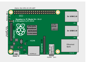
There are lot of IOT Gateway devices available, and Raspberry pi, a credit card sized mini computer famous among the electronic hobbyist can also be used a gateway device and suitable coding should be done to get the data from the sensor and push it to the cloud.

Applications of Internet of things

The Internet of things has a lot of potential application in the field of Power, security, smart cities and smart homes. For example a power plant can be completely monitored, a industry can be completely monitored, similarly there are lots and lots of solutions for real world problems and can vary based on the peoples needs.

Thank You


Friday, 24 June 2016

Getting Started with Raspberry PI


The field of embedded System is continuously evolving and lot of improvements and features are getting added up. The Raspberry pi is one of the important embedded system device and evolving as Internet of Things gateway device.

Hardware Description of Raspberry Pi

The Raspberry Pi is next generation credit card sized mini computer with many features as conventional computer and also has GPIO pins that can be used for Microcontroller applications.
The Raspberry Pi has ARM Cortex processor, the single core processor with 700 MHZ clock frequency is used in Raspberry Pi 1 and Quad core processor of clock frequency 900 MHZ and 1200 MHZ is used in R-Pi 2 and R-PI 3 respectively.
The memory is provided to raspberry pi by external SD card, The SD card is also loaded with suitable operating system, the most popular and preferred operating system is Raspbian.
The Pi also has USB ports which enables us to connect keyboard, Mouse , Pen drive, and it also has a HDMI slot to connect the monitor and one slot for camera interface and it also has one slot is provided for connection the LAN cable to access the internet. The Raspberry Pi can be powered by suitable power adapter of prescribed voltage rating.


Various operations on Pi

As described earlier Pi is a mini computer, you can do certain operations as you do in your computer,
like creating a file, deleting file and we can write own program and run it.

If Raspian or other Linux distributed OS is installed, In LX terminal we can perform various operations in raspberry Pi, to create a directory use the command mkdir dirname, for example mkdir pi. To go in to the directory use the command cd, the command "cd pi" will go in to the directory pi.  To Write a C program and run it, first open a suitable editor either "vi" or "nano",Eg "nano helloworld.c" and write your C program and save the program. To save the program in vi editor press Esc and ":wq".To save the program in nano editor press "ctrl+x". To compile the program "gcc helloworld.c" now object file will be created and to run the program type "./a.out", the output will be displayed on the screen.To install any package we can use the following command "sudo apt-get install 'packageName'",for example to install sqlite3 database "sudo apt-get install sqlite3", this will install sqlite3 database in raspberry pi. To install some third-party packages we can use the wget command to install the package.

Accessing GPIO pins

The Raspberry Pi has GPIO( General Purpose Input Output)  pins that can be used to give digital Input or allows us to take digital output. The number of GPIO pins varies from one model of raspberry Pi to another.
The important point to be noted is Analog inputs cannot be given directly to the Raspberry Pi, so we need external device(such as Expander Pi) to read analog input.There are two ways of numbering the I/O pins in Raspberry Pi within RPi.GPIO. The first is using the BOARD numbering system. This refers to the pin numbers on the Pi header of the Raspberry Pi board. The advantage of using this numbering system is that your hardware will always work, regardless of the board revision of the R-Pi. You will not need to rewire your connector or change your code. The second numbering system is the BCM numbers. This is a lower level way of working - it refers to the channel numbers on the Broadcom SOC. You have to always work with a diagram of which channel number goes to which pin on the RPi board. Your script could break between revisions of Raspberry Pi boards.

To access GPIO pins we need to install RPI.GPIO python library. The RPI.GIPO is installed by default in Raspbian, to ensure that it is in the latest version please follow the following steps

1) sudo apt-get update
2) sudo apt-get install python-rpi.gpio python3-rpi.gpio
3) sudo apt-get install python-dev python3-dev

These three command is needed to access the raspberry pi GPIO pins with help of some python code.

Now let us see some python code to write and read digital pins,

Now Let us see simple program that is to set the digital output

import RPi.GPIO as GPIO ## Import GPIO library
GPIO.setmode(GPIO.BOARD) ## Use board pin numbering
GPIO.setup(7, GPIO.OUT) ## Setup GPIO Pin 7 to OUTGPIO.output(7,True) ## Turn on GPIO pin 7


First line of code is to import the library that allows to use to access the GPIO pins via python script
then then the Board pin Numbering is used, to use the BCM pin numbering use the following command GPIO.setmode(GPIO.BCM). The next line of code is to set the particular pin as output and to turn on the pin True is used, to turn off the particular pin False is used. 

Let us another pin used to read digital input

import Rpi.GPIO as GPIO
GPIO.setmode(GPIO.BCM)
GPIO.setup(23, GPIO.IN, pull_up_down = GPIO.PUD_DOWN)
GPIO.setup(24, GPIO.IN, pull_up_down = GPIO.PUD_UP)
while True:
if(GPIO.input(23) ==1):
print(“Button 1 pressed”)
if(GPIO.input(24) == 0):
print(“Button 2 pressed”)
GPIO.cleanup()

To read the input, we need to specify whether the pin is used as Pull_up or Pull_down, these specification is very much necessary to set the particular pin as input. The while true indicates its a infinite loop and GPIO.input(23) is used to read the pin number 23. similarly same is used for pin number 24.

So these are the very basic operations that are performed on the raspberry pi, the raspberry-pi has more capabilities and  can act as IOT gateway device. 

Thank You


Thursday, 14 January 2016

How to Repair mosquito bat

First open the mosquito bat by using screwdriver, Inside bat we will find simple power electronic circuit, consisting of battery, Transistor, resistors, capacitors , diodes and small transformer.The basic function of this circuit is to generate very high voltage across output and electric fence so mosquito will die immediately when it came in contact with fence.
We need a digital Multimeter to check the various electronic components. 
Caution: Never keep Multimeter probes directly on  the electric fence, it may result in damage to Multimeter and even we may face some shock.

Image showing circuit of mosquito bat

Picture of Open the case and examine the circuit board


First Remove the battery and test the battery carefully, check voltage of battery,  if it is a 3 V(DC) battery, when you check with Multimeter it should show same  rated voltage( in fully charged condition), if it indicates 0 or low value  then battery is damaged.

After removing battery, now test the electronic components, for testing electronic components  keep the Multimter in continuity mode, You will hear a buzzer sound when you one probe is touched with other. In continuity mode of Multimeter we can find short Circuits ,suppose if you test a diode and if you hear buzzer sound then diode is short circuited indicates it is damaged.

Now with the help of Multimeter test all the components, in mosquito bat there is less chance of failing of transformer.so first test all other components

In mosquito bat there is more chance of failing of transistor, so check  the transistor  and if it is damaged replace it.
How to check the transistor-
It is better to check the transistor after removing it, So Desolder the transistor from circuit board with help of soldering rod.(Please be careful while using soldering rod,if you have no practice of using it better avoid it using) or use Desoldering tool to remove it carefully.
For NPN transistor Keep one probe(Red) on Base and other(Black) on emitter, Multimeter should indicate some resistance value, when we reverse the probe(Red probe on emitter and Black on Base) it should indicate "1"  Next keep  probe(Red)on base and other(Black) on collector, Multimeter should indicate value and  when you reverse the probe Multimeter should indicate "1" .Now keep one probe in Emitter and other in Base , Multimeter should  indicate value  "1"   and  if you reverse the probe Multimeter should indicate the same-: "1".

For PNP type transistor  when probe(Red) on emitter and black on base it should indicate resistance value and  when black probe on emitter and Red probe on base it should indicate "1".Next keep  probe(Red)on base and other(Black) on collector, Multimeter should indicate "1" and  when you reverse the probe of multimeter , Multimeter should indicate resistance value.  Now keep one probe in Emitter and other in Base , Multimeter should  indicate value  "1"  and if you reverse the probe Multimeter should indicate the same-: "1".
If the transistor passes above test it is perfectly good.while testing if you hear a buzzer sound then transistor is damaged, you have to replace new transistor. While replacing please note the number written in transistor(Eg BC 547) and replace it with same number.
From the number of transistor we can find it whether it's NPN or PNP type transistor by checking it's data sheet.

Image showing testing of transistor( But it is not in continuity mode)

Image result for testing bipolar transistor with digital multimeter

After testing of transistor, test the  capacitor, keep one end of capacitor with one probe and other end of capacitor with other probe, in continuity mode if it indicates short circuit ( buzzer sound), capacitor is damaged and we have to replace the capacitor.same way test the diode also.Replace capacitance of same capacitance(in farad) and voltage rating.In similar way test the diodes also.

so replace the electronic component which has failed and connect the battery again and close the bat.Now the mosquito bat should be working

Thank You