Sunday, 27 December 2015

Getting started with Arduino

Introduction to Arduino


Arduino is an open-source prototyping platform based on easy-to-use hardware and software. Arduino is simple to learn and easy to use and we can do many innovative projects with help of arduino. An Arduino board historically consists of an Atmel  8-, 16- or 32-bit AVR  microcontrollerTo do programming in arduino we have to use arduino programming language and arduino software(IDE).We write our program in arduino software(IDE). The Arduino IDE supplies a software library called "Wiring" from the Wiring project, which provides many common input and output procedures.
There are various types of arduino boards available like arduino uno, arduino mega, arduino nano, arduino le0rnado  etc. Based on our need we can choose particular board. Let us start our learning by simple and effective arduino board - arduino uno.
Arduino also has some shields which can interfaced with arduino for specific purpose like GSM shield for using GSM, Ethernet shield for internet. Wifi shield for connecting arduino with wifi etc.these shields are readily available and can be easily interfaced with arduino.

Arduino uno

The Arduino uno has ATMEGA328P microcontroller. To power the arduino simply connect it with USB cable or use proper adaptor for power supply.The operating volate is 5V DC. There are 14 digital I/O pins where we can give digital input or we can take digital output. and out of these 14 pins 6 pins are PWM(pulse width modulation)pins.and there are six analog input pins where we can give analog input.it is used when we are using an analog sensor like temperature or pressure sensor. we can connect these sensors to analog input pins.it also has Rx and Tx pins used for serial communication.which can be used while connecting with GSM. To power the arduino simply connect it with USB cable or use proper adaptor for power supply.The operating volate is 5V DC. Arduino uno uses 16 MHZ quartz crystal for clock input.

Image of Arduino uno


Image result for arduino uno


Programming in Arduino


Let us start by simple program blinking of LED

# define LED_PIN 13
void setup() 
{
pinMode(LED_PIN, OUTPUT); // Enable pin 13 for digital output
}
void loop() 
{ 
digitalWrite(LED_PIN, HIGH); // Turn on the LED 
delay(1000); // Wait one second (1000 milliseconds)
digitalWrite(LED_PIN, LOW); // Turn off the LED 
delay(1000); // Wait one second
}


let us assume that a LED is connected to pin 13.This is the simple program to make led blink for every second.At first we are defining pin no 13 as LED_PIN. we can define it by any name like #define LED 13; or #define Light 13.what ever name we are defining we have to use that in our program.instead of # define we can also use like this -  int LED_PIN=13; or # define LED_PIN 13.

Every arduino program has two functions
1) void setup()-Runs only one
2)  void loop()- runs infinitely 

In void setup() we will be assigning whether given pin is used as input or output.so in this program we have assigned LED_PIN( pin 13) as output.so this pin should be used as output not as input.

void loop ()- our actual coding starts here, we write our program/logic here.In the above program first statement of void loop () is digitalWrite(LED_pin, High). The function of digital write () is to make specified pin high or low.In above statement  pin 13 will be high and LED which is connected to pin 13 will glow.and next we are calling delay function, here we are providing a delay of 1 second,so pin will remain high for at least one second, the next statement is digitalWrite(LED_PIN, LOW);, this will make pin 13 as low and LED will turn off and again we are calling delay function, so LED will be off for at least one second.This code keeps on repeating indefinitely and LED continuously blinks.

Here we are connecting LED to pin 13 directly, suppose if we want to automate a Big lamp, we can connect it directly because Lamp will not glow in 5 Volt output from arduino, so for this purpose we need to use a transistor and a relay. Here transistor will act as a switch, base of transistor is connected to output pin of arduino and if output of arduino is high,  transistor will turn on and relay coil is connected to output of transistor will be energized and with help of relay we can control lamp.if information about transistor is needed refer my article on transistor.

Next let us see another simple program 

int LED_pin =13;
int inpin=7; 
int val=0;
void setup()
{
pinMode(LED_pin,OUTUPT);// enable pin 13 for digital output
pinMode(inpin,INPUT);// enable pin 7 for digital input
}
void loop()
{
val=digitalRead(inpin); // read the digital value and store it in val
digitalWrite(LED_pin,val); // turn on or turn off the led based on the value from val.
}

 Let us assume an LED is connected to pin 13 and a digital input is connected to pin  7.
Here first we are defining LED_pin as 13 and inpin as 7, and we are declaring a variable val.and in setup() part we are defining LED_pin as output and inpin as input. and loop part first statement is 
val=digitalRead(inpin);this will read digital value from the pin no 7 and store it in variable val, the function digitalRead() is used to read value from the specified  digital pin either high or low.and next statement is digitalWrite(LED_pin,val); it means the LED_pin will be high if val is high, ie if input given to pin no 7 is high then value stored in val is high and if input is low and value stored in val is low. so based on the value on "val"the LED connected to pin no 13 will turn on or off.

Saturday, 26 December 2015

How 555 timer works

In most of the industries operations are scheduled according to specific time requirements.In process industry,raw material is processed in different stages.In each stage, raw material is processed at particular time period. so for example process may be heating process and heat may required for 5 minutes.so there is number of applications specific delay is needed. the popularly used electronic circuit of providing delay is 555 timer.and with help of 555 timer we can do many electronic projects as well.

The 555 timer IC is an integrated circuit (chip) used in a variety of timer, pulse generation, and oscillator applications. The 555 can be used to provide time delays, as an oscillator, and as a flip-flop element.lot of electronics projects also done  using 555 timer

PIN DIAGRAM OF 555 TIMER


pin description:


Pin 1 (Ground):
Connects to the 0v power supply.

Pin 2 (Trigger):
Detects 1/3 of rail voltage to make output HIGH. Pin 2 has control over pin 6. If pin 2 is LOW, and pin 6 LOW,  output goes and stays HIGH. If pin 6 HIGH, and pin 2 goes LOW, output goes LOW while pin 2 LOW. This pin has a very high impedance (about 10M) and will trigger with about 1uA.

Pin 3 (Output):
(Pins 3 and 7 are "in phase.") Goes HIGH (about 2v less than rail) and LOW (about 0.5v less than 0v) and will deliver up to 200mA.

Pin 4 (Reset):
Internally connected HIGH via 100k. Must be taken below 0.8v to reset the chip.

Pin 5 (Control):
A voltage applied to this pin will vary the timing of the RC network (quite considerably).

Pin 6 (Threshold):
Detects 2/3 of rail voltage to make output LOW only if pin 2 is HIGH. This pin has a very high impedance (about 10M) and will trigger with about 0.2uA.

Pin 7 (Discharge):
Goes LOW when pin 6 detects 2/3 rail voltage but pin 2 must be HIGH. If pin 2 is HIGH, pin 6 can be HIGH or LOW and pin 7 remains LOW. Goes OPEN (HIGH) and stays HIGH when pin 2 detects 1/3 rail voltage (even as a LOW pulse) when pin 6 is LOW.  (Pins 7 and 3 are "in phase.") Pin 7 is equal to pin 3 but pin 7 does not go high - it goes OPEN.  But it goes LOW and will sink about 200mA.

Pin 8 (Supply):
Connects to the positive power supply (Vs). This can be any voltage between 4.5V and 15V DC, but is commonly 5V DC when working with digital ICs. 


Modes of operation


1) Bistable mode


2 )Monostable mode


3)  Astable Mode

Bistable mode


Image result for bistable mode of ic 555

fig:showing bistable mode of 555 timer

The 555 timer in bistable mode is also known as a flip-flop circuit. A flip-flop circuit alternates between two stable states, in this case the output of electrical current from the output pin.There are only two stable states (on and off) controlled directly by the trigger pin and reset pin.Here no external resistors or capacitors is connected.

Astable Mode


555 timer as astable multivibrator


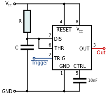
An astable mode of 555 timer, often called a free-running multivibrator, is a rectan­gular-wave generating circuit. Unlike the monostable multivibrator, this circuit does not require any ex­ternal trigger to change the state of the output, hence the name free-running. Before going to make the circuit, make sure your 555 IC is working. For that go through the article: An astable multivibrator can be produced by adding resistors and a capacitor to the basic timer IC, as illustrated in figure. The timing during which the output is either high or low is determined by the externally connected two resistors and a capacitor.in astable mode 2 and 6 is short circuited so no trigger is given.

The general application of astable multivibrator is it will act as square wave generator and duty cycle of the square wave can be controlled.and it can also be used to blinking on and off of light with specific frequency.
percentage duty cycle %D = (R1+R2)/(R1+2R2)X100
frequency of oscillations is given by f=1/T=1/0.693(R1+2R2)C

Monostable Mode


555 timer as monostable multivibrator


 In Monostable mode, external pulse is needed for timer.it is often called as one shot multivibrator. is a pulse generator circuit in which the duration of the pulse is determined by the R-C network,connected externally to the 555 timer
The circuit has only one stable state when trigger is applied, it produces a pulse at the output and return backs to its stable state. Here trigger pulse is applied at 2.
The pulse width is W= 1.1RC ,C in farads, R in ohms, t in seconds.

So electronic hobbyist can develop lot of projects using monostable multivibrator of 555 timer.for example  automatic turning on and off of TV, fan,light etc. here IR can be used as trigger pulse and 555 timer is connected in monostable mode and whenever the trigger is applied output is produced and it is given to transistor(here transistor will act as a switch) and it will in turn on the relay and necessary thing can be controlled.

Conclusion

NE 555 timer is very widely used in the various industrial applications and also in the electronic projects and it it is easy to start develop your own project using 555 timer.


Friday, 25 December 2015

How transistors work


transistor is a semiconductor device used to amplify or switch electronic signals and electrical power. It is composed of semiconductor material with at least three terminals for connection to an external circuit.A voltage or current applied to one pair of the transistor's terminals changes the current through another pair of terminals.
Bipolar transistor has three terminals 
1)Base-control signal
2)Emitter
3)Collector
A small current in the base of the transistor can control large current in the Collector and Emitter terminals.
Generally Bipolar junction Transistor can be classified in to two types
1)NPN Transistor, 2) PNP transistor
NPN transistor means Emitter-N type material, Base- P type material, Collector-N type material,
similarly for PNP transistor-Emitter-P type material, Base- N type material, Collector-P-type material,

Image result for transistor

Fig: showing NPN and PNP transistor
Note: if NPN or PNP is not mentioned, arrow mark towards base indicates PNP transistor.Arrow mark away from the base indicates NPN transistor.
For transistor to work-
1) Emitter- Base junction should be forward biased-Junction has low resistance,
2)Collector-Base junction should be reverse biased-Junction has high resistance.

In transistor Emitter is heavily doped, because it has to supply majority carries.and Collector and Emitter terminals should not be interchanged.and size of Collector is large as compared to base because it has to accept majority carriers.
Transistor can be operated for two purpose
1)Transistor as a Switch
2)Transistor as a amplifier


Transistor as a switch

Transistors are commonly used in digital circuits as electronic switches which can be either in an "on" or "off" state.
Because a transistor’s collector current is proportionally limited by its base current, it can be used as a sort of current-controlled switch. A relatively small flow of electrons sent through the base of the transistor has the ability to exert control over a much larger flow of electrons through the collector.

Image result for transistor as a switch
fig showing transistor as switch.
so with help of base current we can control the large collector current.

Practical application of transistor as switch

Light/ dark activated switch


Image result for light activated switch   


Here photo resistor or  LDR(Light Dependent Resistor) is used as sensor-property of LDR is resistance will decrease when light is applied(few hundred ohms) and resistance will increase in darkness(in mega ohms).
LDR is connected in series with 100 Kilo ohm resistor it forms simple voltage divider connection.
so in darkness voltage drop across Base-Emitter junction increases. so transistor Base-Emitter voltage is above cut off voltage and now transistor starts conducting and current flows through the LED.
similarly when light falls on LDR. Its resistance decreases and voltage across Base-Emitter junction of transistor decreases now transistor will not conduct and current through the LED is zero. and LED will not glow.so by this simple circuit we have made an automatic light which will glow only in darkness and automatically turns off in light. 


Transistor as an amplifier

Image result for transistor as an amplifier


fig:circuit of transistor as an amplifier
The common-emitter amplifier is designed so that a small change in voltage (Vin) changes the small current through the base of the transistor; the transistor's current amplification combined with the properties of the circuit mean that small swings in Vin produce large changes in Vout.
the transistor can be used as a current and voltage amplification.
current gain  hfe = Ic / Ib
A fairly low gain transistor might have a current gain of 20 to 50, while a high gain type may have a gain of 300 to 800 or more
Voltage gain  = change in collector voltage / change in base voltage.
so transistor as amplifier is explained,

Transistor Characteristics:


 Transfer Characteristics
 Input Characteristic.
 Output Characteristic.

Transfer characteristics:


X axis: Base current(mA)
y axis:  collector current(MA)


Transfer Characteristic

The graph of ICE / IBE shown (right) is called the TRANSFER CHARACTERISTIC and the slope of the graph shows the hfe for that transistor.

Input Characteristics:

X axis: Base-Emitter voltage(V)
y axis:  Base current(MA)

Input Characteristic

The INPUT CHARACTERISTIC (right), a graph of base emitter current IBE against base emitter voltage. Initially the transistor is not conducting because the voltage is below cut in voltage or knee voltage. when the voltage is above knee voltage base current flows.


 Output Characteristic.


X axis: Collector-Emitter voltage(V)
y axis:  collector current(MA)


Output Characteristic
 shows the OUTPUT CHARACTERISTIC whose slope gives the value of output conductance.for small values of base current the corresponding collector current is low and if base current is increased, collector current is also increased.

These are the various characteristics of transistor.

Conclusion

Most of the analog and digital electronic  circuits and logic gates  are build using transistors.so knowing the working of transistor is very important